I took and passed the CCNA Security yesterday! I haven't completed the writeup yet for my site-site VPN lab but am still planning on posting it soon. After I finish a few more of my CCNA Security related notes, I'm aiming to move on to working for the CCNP Security, and sharpening my programming abilities as I'd like to go for offensive security's OSCP.
Lab Reconfiguration
I've also decided to do some major reconfiguration to the lab that I designed originally. I am fairly irritated with the slow speeds that I am stuck with using the 2600's and serial links, so I am currently overhauling my cisco lab. I have decided to try using GNS3 to virtualize mostly everything, but with a twist. I'll be using multiple GNS3 hosts within ESXi, and on a second physical host. Following this method, I should be able to construct even more complex topologies without being limited on physical problems such as WIC cards and memory resources, and break out the virtual connections to my physical layer 3 switches and other physical devices such as my ASA and IPS 4260 appliance (yes I added another piece to my lab..)
Saturday, June 15, 2013

Tuesday, June 11, 2013
Clearing Cisco Self Signed Certificates and Keys
Quick post here, for future reference for myself and anyone else with this issue. As you know (or will find out), if you copy a config from one device to another, you'll need to generate new keys or certificates for both your SSH connection and HTTPS. Another issue is if you are using CCP and accidentally happen to deny the use of one of your managed devices because you didn't trust the self signed cert with the CCP pop up window (I did this accidentally) If you don't want to hunt for the cert in IE, and are using lab equipment, here are the quick and easy fixes for removing existing self signed RSA keys for both HTTPS and for SSH/general purpose keys:
First, launch a show run to find out the name of your self signed certificate. This is for the example of regnerating your HTTPS certificate. Then when you find the name, you can append a "no" in front of it. If you need to generate a new SSH key, I recommend doing this over a console connection so you don't lose your SSH connection. Afterwhich you can regenerate the new keys.
My show run displayed this for the name, along with the beginning of key used for SSH
!
crypto pki trustpoint TP-self-signed-815397456
enrollment selfsigned
subject-name cn=IOS-Self-Signed-Certificate-815397456
revocation-check none
rsakeypair TP-self-signed-815397456
!
!
crypto pki certificate chain TP-self-signed-815397456
certificate self-signed 01
30820243 308201AC A0030201 02020101 300D0609 2A864886 F70D0101 04050030
I then used the following commands to wipe my existing self signed certificate and generate new RSA keys
First, launch a show run to find out the name of your self signed certificate. This is for the example of regnerating your HTTPS certificate. Then when you find the name, you can append a "no" in front of it. If you need to generate a new SSH key, I recommend doing this over a console connection so you don't lose your SSH connection. Afterwhich you can regenerate the new keys.
My show run displayed this for the name, along with the beginning of key used for SSH
!
crypto pki trustpoint TP-self-signed-815397456
enrollment selfsigned
subject-name cn=IOS-Self-Signed-Certificate-815397456
revocation-check none
rsakeypair TP-self-signed-815397456
!
!
crypto pki certificate chain TP-self-signed-815397456
certificate self-signed 01
30820243 308201AC A0030201 02020101 300D0609 2A864886 F70D0101 04050030
I then used the following commands to wipe my existing self signed certificate and generate new RSA keys
ISP_1(config)#no crypto pki trustpoint TP-self-signed-815397456
% Removing an enrolled trustpoint will destroy all certificates
received from the related Certificate Authority.
Are you sure you want to do this? [yes/no]: y
% Be sure to ask the CA administrator to revoke your certificates.
ISP_1(config)#crypto key zeroize rsa
% All RSA keys will be removed.
% All router certs issued using these keys will also be removed.
Do you really want to remove these keys? [yes/no]: y
ISP_1(config)#crypto key generate rsa
The name for the keys will be: ISP_1.isp.com
Choose the size of the key modulus in the range of 360 to 2048 for your
General Purpose Keys. Choosing a key modulus greater than 512 may take
a few minutes.
How many bits in the modulus [512]: 1024
% Generating 1024 bit RSA keys, keys will be non-exportable...[OK]
ISP_1(config)#ip http secure-server
% Generating 1024 bit RSA keys, keys will be non-exportable...[OK]
ISP_1(config)#
The issue I experienced, was I swapped hardware for my ISP and datacenter edge lab routers-my ISP router has a more advanced IOS image and more RAM, and with it I can run IOS IPS and the zone based firewall. I just need the ISP router to route, and I wanted these security functions for my lab purposes. So when I swapped the config files, I didn't paste in the keys (I'm using putty, and generally pasting in that much information causes..fun things to happen) but realized I needed to wipe my existing self signed cert and SSH keys and create new ones for both devices.
Sunday, June 9, 2013
Lab Part 3: Secure the Routers
Overview
This part of the lab assumes that all of the routers in the topology below have configured routing protocols. All three of the "corp owned" routers branch off the ISP_1 router (I know, no redundancy but I only have so many WIC cards to play with). As seen in the more focused topology below, the corp owned routers and ISP_1 routers use OSPF area 1 for their routing protocol. An area 0 backbone will later be added to expand the topology. The corp_border router also runs EIGRP for the 207.100.100.0/27 network, and this route is redistributed into OSPF area 1. Since this mostly delves back into basic CCNA R/S, I won't be reviewing how the routing was configured, but instead will be focusing on CCNA Security implementation topics. The lab assumes completed routing, where the ASA can ping all of the external router interfaces. Internal subnets will all utilize NAT to simulate a real world environment, as the ISP will be filtering all RFC1928 addresses from entering its interfaces.
Topology:

Security Policy
To give a roadmap or outline to the configurations, here is the basic security policy for the lab:
-Only administrators from the IP address 172.16.100.10 should have management access to corporation owned network equipment
-All network management tools and protocols will use encryption whenever possible
-Centralized authentication, authorization, and accounting must be used
-All edge routers will be hardened from outside attacks
-There will be no plaintext passwords stored on network config files
-All edge routers will shield their internal networks through the use of IOS software firewalls
-All logging will be centralized and encrypted in transit to the logging server
-A full mesh site to site VPN tunnel will be used across the enterprise edge routers
Lab Topics
This part of the lab covers the following:
Implement AAA
Implement security on Cisco routers
Implement zone based firewall policy using CCP
Implement IP ACLs
Implement secure network management
Implement AAA
We'll start by doing a mock configuration of AAA using CCP on the Corp border router. Then we will implement a local user AAA config on all of the routers. Remember from the CCNA that in order to use CCP, you need to have HTTP (preferably HTTPS) running, a local user on the router, and set http to authentication local.
CORP_BORDER(config)#ip http secure-server
CORP_BORDER(config)#ip http authentication local
CORP_BORDER(config)#username admin pri
CORP_BORDER(config)#username admin privilege 15 password cisco
CORP_BORDER(config)#do wr

Next, we'll harden and secure the edge routers.
Securing the Router with CCP
For certification purposes, I'll first cover securing the router with CCP. You can either use the command line auto-secure command, use CCP's security Audit and then fix items individually, or use one step lock down to secure the router. Using CCP, navigate down to Security->Security Audit

The wizard itself for the audit is fairly self explanatory. At the end, you will be presented with your audit report.

You can either use one-step lock down, or fix the items individually. If you were in a production environment, you'd probably want to just check the items individually to verify CCP doesn't break anything that you do in fact need.

I selected all, except enabling the firewall as this would enable the CBAC firewall on my older routers.
Implement Zone Based Firewall with CCP
Unfortunately, only one of my routers has the capability to run the ZBF. The others only support CBAC. So I'll walk through the configuration of the ZBF but will not be implementing it at this time.
To configure the ZBF in CCP, navigate to Security->Firewall->Firewall.

The wizard is fairly self explanatory-select your trusted inside and untrusted outside interfaces. For my purposes, I set all of but one of the serial interfaces to trusted. Next you are presented with a screen with a slider bar to determine what level of security for the firewall to run.

Before completion, the wizard will display what commands will be relayed to the firewall.

Implement IP ACLs
Our mock ISP has a policy of prohibiting IRC traffic. As a basic mitigation, ACLs will be applied inbound on all serial interfaces to try deny irc traffic following the commonly used TCP port number of 194. Of course using something that inspects at the application layer (like the ZBF) would be more effective here, but this is just a refresh on configuring access lists.
ISP_1(config)#ip access-list extended PACKET-FILTER
ISP_1(config-ext-nacl)#deny tcp any any eq irc log
ISP_1(config-ext-nacl)#permit ip any any
ISP_1(config-ext-nacl)#exit
ISP_1(config)#int s1/0
ISP_1(config-if)#ip access-group PACKET-FILTER in
ISP_1(config-if)#int s1/1
ISP_1(config-if)#ip access-group PACKET-FILTER in
ISP_1(config-if)#int s1/2
ISP_1(config-if)#ip access-group PACKET-FILTER in
ISP_1(config-if)#int s1/3
ISP_1(config-if)#ip access-group PACKET-FILTER in
Now, the ISP has also decided to to block any inbound addresses that match those listed in RFC 1918 across all interfaces. All RFC 1918 blocks as the source or destination will be denied. Since the permit ip any any list is line number 20, we will configure these lines as 11-16. Remember that ACL's use wildcards. This would be simpler with the creation of object groups, but this router IOS does not support object-groups.
ISP_1#show ip access-lists
Extended IP access list PACKET-FILTER
10 deny tcp any any eq irc log
20 permit ip any any
ISP_1#conf t
ISP_1(config)#ip access-list extended PACKET-FILTER
ISP_1(config-ext-nacl)#11 deny ip 10.0.0.0 0.255.255.255 any log
ISP_1(config-ext-nacl)#12 deny ip 172.16.0.0 0.15.255.255 any log
ISP_1(config-ext-nacl)#13 deny ip 192.168.0.0 0.0.255.255 any log
ISP_1(config-ext-nacl)#14 deny ip any 10.0.0.0 0.255.255.255 log
ISP_1(config-ext-nacl)#15 deny ip any 172.16.0.0 0.15.255.255 log
ISP_1(config-ext-nacl)#16 deny ip any 192.168.0.0 0.0.255.255 log
ISP_1(config-ext-nacl)#exit
ISP_1(config)#exit
ISP_1#show ip acces
Extended IP access list PACKET-FILTER
10 deny tcp any any eq irc log
11 deny ip 10.0.0.0 0.255.255.255 any log
12 deny ip 172.16.0.0 0.15.255.255 any log
13 deny ip 192.168.0.0 0.0.255.255 any log
14 deny ip any 10.0.0.0 0.255.255.255 log
15 deny ip any 172.16.0.0 0.15.255.255 log
16 deny ip any 192.168.0.0 0.0.255.255 log
20 permit ip any any
Implement Secure Network Management
So far, an audit has been run on all of the edge routers, unnecessary services have been disabled, and the routers have been hardened. Hypothetically, a ZBF has been implemented on each border router, and AAA with TACACS has been configured (for this topology, you would either need a VPN setup, or have individual TACACS servers at each site). The ISP router is filtering out any traffic sourced or destined to a private IP address, along with any IRC traffic. So far, we've met a few items for the security policy. I've highlighted the items in red which are still not in compliance:
-Only administrators from the IP address 172.16.100.10 should have management access to corporation owned network equipment
-All network management tools and protocols will use encryption
Only SSH and HTTPS are being used to manage remote devices
-Centralized authentication, authorization, and accounting must be used
AAA with a centralized TACACS server was hypothetically configured
-All edge routers will be hardened from outside attacks
CCP audit was run, which disabled unused services, and enabled numerous security features on untrusted interfaces
-There will be no plaintext passwords stored on network config files
CCP audit enabled service password encryption, along with forcing the creation of an enable secret
-All edge routers will shield their internal networks through the use of router firewalls
ZBF was hypothetically created on all edge routers
-All logging will be centralized and encrypted in transit to the logging server
-A full mesh site to site VPN tunnel will be used across the enterprise edge routers
The last three items will be covered in the next lab, which will configure the full mesh site to site VPN tunnels between the remote sites. The management access will be restricted by an access-class applied to the VTY lines and the http server. Logging will be encrypted within the VPN tunnels across the public WAN links, and SNMPv3 will be used whenever possible. A network monitoring system will be setup to collect these logs.
This part of the lab assumes that all of the routers in the topology below have configured routing protocols. All three of the "corp owned" routers branch off the ISP_1 router (I know, no redundancy but I only have so many WIC cards to play with). As seen in the more focused topology below, the corp owned routers and ISP_1 routers use OSPF area 1 for their routing protocol. An area 0 backbone will later be added to expand the topology. The corp_border router also runs EIGRP for the 207.100.100.0/27 network, and this route is redistributed into OSPF area 1. Since this mostly delves back into basic CCNA R/S, I won't be reviewing how the routing was configured, but instead will be focusing on CCNA Security implementation topics. The lab assumes completed routing, where the ASA can ping all of the external router interfaces. Internal subnets will all utilize NAT to simulate a real world environment, as the ISP will be filtering all RFC1928 addresses from entering its interfaces.
Topology:

Security Policy
To give a roadmap or outline to the configurations, here is the basic security policy for the lab:
-Only administrators from the IP address 172.16.100.10 should have management access to corporation owned network equipment
-All network management tools and protocols will use encryption whenever possible
-Centralized authentication, authorization, and accounting must be used
-All edge routers will be hardened from outside attacks
-There will be no plaintext passwords stored on network config files
-All edge routers will shield their internal networks through the use of IOS software firewalls
-All logging will be centralized and encrypted in transit to the logging server
-A full mesh site to site VPN tunnel will be used across the enterprise edge routers
Lab Topics
This part of the lab covers the following:
Implement AAA
Implement security on Cisco routers
Implement zone based firewall policy using CCP
Implement IP ACLs
Implement secure network management
Implement AAA
We'll start by doing a mock configuration of AAA using CCP on the Corp border router. Then we will implement a local user AAA config on all of the routers. Remember from the CCNA that in order to use CCP, you need to have HTTP (preferably HTTPS) running, a local user on the router, and set http to authentication local.
CORP_BORDER(config)#ip http secure-server
CORP_BORDER(config)#ip http authentication local
CORP_BORDER(config)#username admin pri
CORP_BORDER(config)#username admin privilege 15 password cisco
CORP_BORDER(config)#do wr
Now we should be able to login via CCP and mock a setup of AAA using a TACACS+ server. Throughout this lab, I am connected behind the Corp Border ASA.
A few bits of advice here in getting CCP to run correctly-I'm using Windows 7 64bit and IE 10 for my lab computer. You need to install the java plugin for IE. Additionally, you need to enable compatibility view on IE for CCP by adding your localhost address to the compatibility page (tools->compatibility view settings). Last, you must launch CCP as administrator. Otherwise you will be greeted by CCP freezing on "finding ports".
So first, when you get CCP running, you're presented with the select/manage community window. Enter in the IP address for the router, followed by user/password, select the "connect securely" checkbox to connect over HTTPS (and for commands to be relayed via SSH and not telnet..), and click Ok.
After you add the device, you'll need to discover it by clicking the discover box at the bottom of the page.

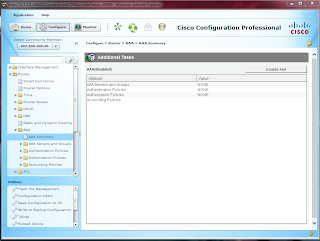
Mine discovered with warnings-my routers are fairly old (2600XMs) so not everything within CCP is functional, but I have enough functionality for this lab. To create the AAA configuration, select the Configure button and browse down to Router->AAA->AAA Summary. Click on the Enable AAA button.

There will be a brief pause, followed by a second pop up window displaying the commands that will be sent over to the devices running configuration. Click Deliver. Now that there is a backup AAA command set in place, we'll configure the TACACS+ server line, and then create a method list for login and authentication via TACACS. Click on the AAA Servers and Groups drop down folder in the navigation pane, and then select Servers. Select Add. You can then enter in an IP for the TACACS+ server, along with the secure key for authenticating the router against TACACS. If you click Ok, it will show you that it will deliver the commands to the router:
tacacs-server host 172.16.100.105 key 0 ********
no ip tacacs source-interface
no tacacs-server timeout
I clicked cancel here, as I do not have a TACACS+ server, but to complete the mock configuration, you would next need to create the method list for authentication and exec authorization using TACACS+ as a method (and preferably local as a second method incase the TACACS server is unreachable..), and apply that method list to the desired interfaces. You can do so by clicking "add" under AAA->Authentication-> Login and AAA->Authorization->Exec. You simply define the methods you'd like to use, give it a name, and click ok. To apply your custom method lists, you'll have to select Router Access->VTY and select your custom method lists to apply them against the VTY lines.
I'm going to use a basic AAA configuration to use local authentication on all the routers. First I'll create a local user, then I'll use the following 3 commands to apply the default method list against the console, VTY, and aux lines. Don't forget to create a local user-it's never a fun experience to enable AAA, copy run start, exit the router, and have no local user to login with-or if you are using TACACS, not to have local defined as a second method. Don't ask me how I know this.
CORP_BORDER(config)#aaa new-model
CORP_BORDER(config)#aaa authentication login default local
CORP_BORDER(config)#aaa authorization exec default local
Securing the Router with CCP
For certification purposes, I'll first cover securing the router with CCP. You can either use the command line auto-secure command, use CCP's security Audit and then fix items individually, or use one step lock down to secure the router. Using CCP, navigate down to Security->Security Audit

The wizard itself for the audit is fairly self explanatory. At the end, you will be presented with your audit report.

You can either use one-step lock down, or fix the items individually. If you were in a production environment, you'd probably want to just check the items individually to verify CCP doesn't break anything that you do in fact need.

I selected all, except enabling the firewall as this would enable the CBAC firewall on my older routers.
Implement Zone Based Firewall with CCP
Unfortunately, only one of my routers has the capability to run the ZBF. The others only support CBAC. So I'll walk through the configuration of the ZBF but will not be implementing it at this time.
To configure the ZBF in CCP, navigate to Security->Firewall->Firewall.

The wizard is fairly self explanatory-select your trusted inside and untrusted outside interfaces. For my purposes, I set all of but one of the serial interfaces to trusted. Next you are presented with a screen with a slider bar to determine what level of security for the firewall to run.

Before completion, the wizard will display what commands will be relayed to the firewall.

Implement IP ACLs
Our mock ISP has a policy of prohibiting IRC traffic. As a basic mitigation, ACLs will be applied inbound on all serial interfaces to try deny irc traffic following the commonly used TCP port number of 194. Of course using something that inspects at the application layer (like the ZBF) would be more effective here, but this is just a refresh on configuring access lists.
ISP_1(config)#ip access-list extended PACKET-FILTER
ISP_1(config-ext-nacl)#deny tcp any any eq irc log
ISP_1(config-ext-nacl)#permit ip any any
ISP_1(config-ext-nacl)#exit
ISP_1(config)#int s1/0
ISP_1(config-if)#ip access-group PACKET-FILTER in
ISP_1(config-if)#int s1/1
ISP_1(config-if)#ip access-group PACKET-FILTER in
ISP_1(config-if)#int s1/2
ISP_1(config-if)#ip access-group PACKET-FILTER in
ISP_1(config-if)#int s1/3
ISP_1(config-if)#ip access-group PACKET-FILTER in
Now, the ISP has also decided to to block any inbound addresses that match those listed in RFC 1918 across all interfaces. All RFC 1918 blocks as the source or destination will be denied. Since the permit ip any any list is line number 20, we will configure these lines as 11-16. Remember that ACL's use wildcards. This would be simpler with the creation of object groups, but this router IOS does not support object-groups.
ISP_1#show ip access-lists
Extended IP access list PACKET-FILTER
10 deny tcp any any eq irc log
20 permit ip any any
ISP_1#conf t
ISP_1(config)#ip access-list extended PACKET-FILTER
ISP_1(config-ext-nacl)#11 deny ip 10.0.0.0 0.255.255.255 any log
ISP_1(config-ext-nacl)#12 deny ip 172.16.0.0 0.15.255.255 any log
ISP_1(config-ext-nacl)#13 deny ip 192.168.0.0 0.0.255.255 any log
ISP_1(config-ext-nacl)#14 deny ip any 10.0.0.0 0.255.255.255 log
ISP_1(config-ext-nacl)#15 deny ip any 172.16.0.0 0.15.255.255 log
ISP_1(config-ext-nacl)#16 deny ip any 192.168.0.0 0.0.255.255 log
ISP_1(config-ext-nacl)#exit
ISP_1(config)#exit
ISP_1#show ip acces
Extended IP access list PACKET-FILTER
10 deny tcp any any eq irc log
11 deny ip 10.0.0.0 0.255.255.255 any log
12 deny ip 172.16.0.0 0.15.255.255 any log
13 deny ip 192.168.0.0 0.0.255.255 any log
14 deny ip any 10.0.0.0 0.255.255.255 log
15 deny ip any 172.16.0.0 0.15.255.255 log
16 deny ip any 192.168.0.0 0.0.255.255 log
20 permit ip any any
ISP_1#wr
So far, an audit has been run on all of the edge routers, unnecessary services have been disabled, and the routers have been hardened. Hypothetically, a ZBF has been implemented on each border router, and AAA with TACACS has been configured (for this topology, you would either need a VPN setup, or have individual TACACS servers at each site). The ISP router is filtering out any traffic sourced or destined to a private IP address, along with any IRC traffic. So far, we've met a few items for the security policy. I've highlighted the items in red which are still not in compliance:
-Only administrators from the IP address 172.16.100.10 should have management access to corporation owned network equipment
-All network management tools and protocols will use encryption
Only SSH and HTTPS are being used to manage remote devices
-Centralized authentication, authorization, and accounting must be used
AAA with a centralized TACACS server was hypothetically configured
-All edge routers will be hardened from outside attacks
CCP audit was run, which disabled unused services, and enabled numerous security features on untrusted interfaces
-There will be no plaintext passwords stored on network config files
CCP audit enabled service password encryption, along with forcing the creation of an enable secret
-All edge routers will shield their internal networks through the use of router firewalls
ZBF was hypothetically created on all edge routers
-All logging will be centralized and encrypted in transit to the logging server
-A full mesh site to site VPN tunnel will be used across the enterprise edge routers
The last three items will be covered in the next lab, which will configure the full mesh site to site VPN tunnels between the remote sites. The management access will be restricted by an access-class applied to the VTY lines and the http server. Logging will be encrypted within the VPN tunnels across the public WAN links, and SNMPv3 will be used whenever possible. A network monitoring system will be setup to collect these logs.
Lab Part 2: ASA and the ASDM
Configuring the ASA with ASDM






Now that we have basic access to the ASA, we'll continue on with the configurations through ASDM. From reading the study material and the exam blueprints, it looks like you are expected to know how to configure basic access lists, NAT, PAT, and some setup through ASDM. So in this lab, we'll cover exactly that.
Assuming you followed the first part of the lab, you should be able to reach the ASA at https://172.16.100.1
Since you restricted management access only from 172.16.100.10, your PC will need this address.
Either run ASDM by downloading it locally and running it, or by using the java web start option. Since I was battling some java issues at the time, I used the java web start app. (You can click on these images to expand them)

Now that we have entered ASDM, it's time to perform some basic configurations.
Review Firewall Configuration
Lets start by reviewing our CLI commands, and seeing what that looks like within ASDM (you should know how to configure that here as well). We'll look at our interfaces, security levels, and associated VLANs. Click on the configuration tab, and then on the panel on the left, click on interfaces.

Here we can see the interface names on the first column. The first row has no name, as these interfaces are all assigned to VLAN 1 by default (we didn't set them up-eth0/1 was reserved for the DMZ, and none of the others were configured). The switchports will be shut down by default. We will go ahead and disable this interface for now.
Click edit, which brings up this window.

You can see that eth0/1, and eth 0/3-7 are assigned to this interface (VLAN 1). You should be able to see from here how you would configure this if you had just setup the ASA with a barebones configuration for accessing it via ASDM-an IP address assigned to VLAN 1, an ifname, and bringing up say eth0/0 or whichever switchport you wanted to use for the inside. Then within ASDM, you could configure your other interfaces (SVIs for those of us with the 5505), assign the name, security level, and assign switchports. If you were to create a new interface, you could set its VLAN ID under the advanced tab.
A special note for the ASDM-generally speaking, when you configure something within an edit window, it will not apply this configuration to the running-config until you click the Apply button at the bottom of the window. If you click the Save tab on the menu bar (with home, configuration, monitoring, etc), it will backup the running config to startup config.
Now, select the Switch Ports tab.

Here you can verify the configuration we implemented with the CLI- switchports 0/0 and 0/2 are up. 0/0 is assigned to interface VLAN 10 (outside), and 0/2 is assigned to VLAN 100 (inside). All other interfaces are set to their default configurations of VLAN 1, disabled.
I have the basic ASA license, so I am unable to fully configure a DMZ at this point in time, so lets move on to configuring our static routes.
Configure Routing
If we want our traffic to go anywhere, we will need to set some default routes for the ASA. Lets get to the routing configuration tab by clicking on Device Setup>Routing>Static Routes

We have an empty table-we need to configure some routes. Now according to our overall topology, we have our corp border router connected to our ASA. (not setup yet, but will be in the next lab). The interface facing us is on the 207.100.100.0/27 block, with IP address 207.100.100.30. We will configure a default route to that gateway IP address. With our simple configuration, the ASA will know to send traffic addressed to the inside address range of 172.16.100.0/24 out its directly connected interface, VLAN 100.
Click the add button, and you will see the static route configuration window.
This can be slightly confusing at first. Which interface should you add the default route to? The answer, is that it is quite similar to configuring a static route on a regular IOS device. Remember on a router, the command is ip route <destination network> <destination mask> <gateway IP> OR <forwarding interface>
In this case, the command on the ASA CLI is route <ifname> <destination net> <destination mask> <gateway IP>
So keep this in mind while within the GUI-the interface name is the one by which the traffic will be routed out, following the configured route settings. So in this instance, our default route should be added to the outside interface, as configured below

Make sure to click apply, and then save to your startup config if desired by clicking the Save icon. Now, on to understanding behavior regarding security levels and configuring access rules.
Access Rules and Security Levels
Start by clicking on Firewall under device setup, while still within the configuration pane.

By default, the firewall will use its security levels for stateful filtering.
Any traffic sourced from higher security interfaces is permitted out to lower security interfaces
Reply traffic from lower security interfaces is permitted back to higher security interfaces
Any traffic from lower security -> higher security interfaces is denied implicitly.
Since we assigned the outside interface to security level 0, and the inside interface to security level 100, only traffic initially sourced from the inside to outside, and its associated reply traffic from the outside, will be permitted. What is important to keep in mind, is if we create an access rule, what happens to this filtering behavior in regards to the security levels. If you create an access rule for the inside, say filtering any IRC traffic from exiting, the ACL will add an implicit deny any at the end of the statement. This can cause some confusion as the behavior changes from the above security level rules, to using the ACLs. The stateful reply traffic will remain the same however.
I will use the packet tracer tool to demonstrate this behavior. The packet tracer tool is a very useful feature which can act as a policy review to let you know what types of traffic will be denied or permitted, without having to send actual traffic through the firewall.
Start by configuring your inside incoming ACL to filter any IRC traffic.

Now you will see your access rule icons change from the "any, any less secure networks" to deny any any IRC.

There is an associated global deny any any rule attached onto this ACL-we can confirm that all of the remaining traffic will be denied (probably something we don't want to happen) by using the packet tracer tool. The tool is located under Tools. We'll emulate a user attempting to browse out to their favorite business site, facebook (simulated IP).

As you can see, the traffic would be denied. You can drill down into the Access-List phase and see which rule denied this traffc.

See how it says "Config Implicit Rule". Remember our rule with access lists? There is always a implicit deny rule at the end of every access rule. To correct this, we will need to add a permit any at the end of our inbound filtering statement for the inside interface. Make sure you add the rule after your deny rule-same logic with standard/extended ACLs on IOS systems, the rules are processed in order and processing will end at the first matched statement. Don't forget to click the apply button and save the configuration to running config.
After you do so, lets run the packet tracer rule again.
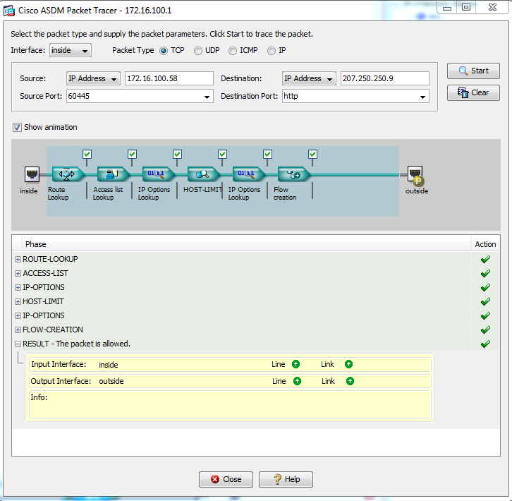
So going out, according to packet tracer, our configuration will work. We still have a problem, however. How will traffic from our facebook browser be returned to that inside address of 172.16.100.58? Since there is no NAT or PAT configured yet, our traffic will likely be filtered out within the ISP to begin with-this is an unroutable, private IP. Lets fix this issue.
Configure NAT/PAT
You can see the nat configuration directly below Access Rules in the pane on the far left. Click on NAT Rules to get started.

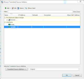
Now, to fix our NAT issue. We will click on the add drop down button, and select add NAT rule. We want to configure PAT for our entire 172.16.100.0/24 block of addresses, with PAT overload so all of our inside hosts can have their IPs translated using the ASA's outside interface IP.

We'll set the source interface to inside, the destination interface to outside, the source, destination, and service fields to ANY. Now under the translated packet, we will select source NAT type of Dynamic PAT (hide). To set the source address to translate into, click on the ... button and select the outside interface

Your rule table should look like this

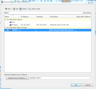
Lets say we wanted to refine these rules abit more, and specify that only hosts from the internal network of 172.16.100.0/24 should be matched to have their addresses translated. To accomplish this, we need to create a network object. To allow for better organization, we should ideally create a network object group, which we can later add more network objects into. We can do this from within the nat rule window. So edit your rule again, and under the source address for the match section, click on the ... button again to draw up your selection. Now you can click on the add drop down, and select network object group.

Lets call this group "INSIDE-HOSTS", with a description of "hosts inside the corporate network". You cannot have spaces in the group name, but you may add spaces in the description. Now from within this window, you can add your network object groups. Click the radio button Create new Network Object member. Set a name if desired, set the type to network, and set the IP address to 172.16.100.0 with a mask of 255.255.255.0. You can also add in a description if desired. Click Add >> when you are finished, and then OK. Your window should look like this

Now, from your Browse Original Source Address window, you can select your INSIDE-HOSTS network object group, or just select the network object of VLAN100. In the real world, this selection would depend on your network design. We will select our newly created network object group of INSIDE-HOSTS.

Click ok, and now your NAT rule will apply to any network object that is a member of INSIDE-HOSTS. In our configuration, that would be any host inside our VLAN 100 network of 172.16.100.0.
Configure ICMP Inspection
Now we just have one last component to configure. Have you noticed that you are unable to ping the neighboring router's address (if you are following the topology) at 207.100.100.30, from your management workstation off the inside interface of the ASA? In fact, any ICMP traffic crossing the ASA, and returning through it will fail.

By default, the ASA won't statefully inspect icmp traffic. This means that any ping attempts crossing the firewall will fail, as there is no stateful inspection, the traffic cannot be returned. For troubleshooting purposes, lets enable this. Below the NAT Rules icon is Service Policy Rules. It is within here that we can get ICMP inspection enabled.

Right click and edit the inspection default policy. This policy is present on the default configuration of the ASA
Now browser over to default inspections. You can see that ICMP is listed, by why isn't working? The answer is within the Rule Actions tab-these are the actions (hence the name) that are applied to traffic that meets the inspection criteria.

Click on the rule actions tab, browse down until you see ICMP-you will see that it is unchecked. Check the box next to ICMP, click ok, and apply the configuration. Now try to ping again from the inside interface to the neighboring router. Your ping should be successful this time.

That completes our ASA configuration for now, later we will return to configure the VPNs!
CCNA Security Review
CCNA Security: Implementation
In the next post, I'll be picking up where I left off with the ASA lab, but I want to list out what I'll primarily be focusing on in the next series of posts. I'll still be reviewing the configuration for the lab, but focusing in on these key topics from the CCNA Security Syllabus:
Implement security on Cisco routers
Implement AAA
Implement IP ACLs
Implement secure network management
Implement VLANs and trunking
Implement spanning tree
Implement zone based firewall policy using CCP
Implement ASA
Implement NAT and PAT
Configure Cisco IOS IPS using CCP
Implement IOS IPSec site-site VPN with PSK auth
Implement SSL VPN using ASDM
We've performed the basic setup of the ASA, now we need to configure a few access control functions, and then configure NAT and PAT, and besides the VPN configurations, we'll have the ASA covered.
Moving on from there, I'll be reviewing configuring the datacenter, corp, and branch routers following the CCNA Security implementation topics-secured following the network foundation protection topics, locally hardened, and an example of ZBF configuration using CCP. The datacenter edge router will have NAT/PAT configured via CCP. The ISP router will be configured with an IP ACL to review on access lists.
The internal switches will be configured following what is expected of the exam blueprint- secure management, spanning tree protection, port security. VLANs and trunks will of course be setup, this goes without saying considering the topology.
All devices will be configured for snmp logging, and a later date, this data will be fed to a network monitoring system. For now, AAA local will be used until I have a tacacs server setup, but I will review the tacacs commands.
As a demonstration, I will configure IOS IPsec site to site with PSK between two of the routers, but will tear this down and replace it with a full mesh site to site tunnels between the routers and the ASA using digital certificates for authentication instead of PSK.
A SSL VPN will be configured for remote users using the ASDM
I don't have a router capable of running IOS IPS so I won't be able to demonstrate that implementation step.
That covers most if not all of the implementation topics listed on the exam blueprint as of today.
In the next post, I'll be picking up where I left off with the ASA lab, but I want to list out what I'll primarily be focusing on in the next series of posts. I'll still be reviewing the configuration for the lab, but focusing in on these key topics from the CCNA Security Syllabus:
Implement security on Cisco routers
Implement AAA
Implement IP ACLs
Implement secure network management
Implement VLANs and trunking
Implement spanning tree
Implement zone based firewall policy using CCP
Implement ASA
Implement NAT and PAT
Configure Cisco IOS IPS using CCP
Implement IOS IPSec site-site VPN with PSK auth
Implement SSL VPN using ASDM
We've performed the basic setup of the ASA, now we need to configure a few access control functions, and then configure NAT and PAT, and besides the VPN configurations, we'll have the ASA covered.
Moving on from there, I'll be reviewing configuring the datacenter, corp, and branch routers following the CCNA Security implementation topics-secured following the network foundation protection topics, locally hardened, and an example of ZBF configuration using CCP. The datacenter edge router will have NAT/PAT configured via CCP. The ISP router will be configured with an IP ACL to review on access lists.
The internal switches will be configured following what is expected of the exam blueprint- secure management, spanning tree protection, port security. VLANs and trunks will of course be setup, this goes without saying considering the topology.
All devices will be configured for snmp logging, and a later date, this data will be fed to a network monitoring system. For now, AAA local will be used until I have a tacacs server setup, but I will review the tacacs commands.
As a demonstration, I will configure IOS IPsec site to site with PSK between two of the routers, but will tear this down and replace it with a full mesh site to site tunnels between the routers and the ASA using digital certificates for authentication instead of PSK.
A SSL VPN will be configured for remote users using the ASDM
I don't have a router capable of running IOS IPS so I won't be able to demonstrate that implementation step.
That covers most if not all of the implementation topics listed on the exam blueprint as of today.
Sunday, June 2, 2013
Lab part 1: Initial ASA Configuration
At the end of this post you can see the complete topology of what this lab series covers (I couldn't really find another more practical way of cramming everything in, I usually use GNS3 just to create a clean topology quickly). In the first post of the lab, we are going to start with getting an ASA up and running so that ASDM can be used to connect to it. This lab starts with a wiped ASA, and rather then following the CLI startup wizard, it will be configured manually. I think this is the best way to learn as to what is taking place.
Lab Objectives
This lab assumes an ASA 5505 with no initial configuration. These are the requirements for the configuration:- Outside interface, assigned to VLAN 10, security level 0 with an IP of 207.100.100.1/27
- Inside interface, assigned to VLAN 100, security level 100, with an IP of 172.16.100.1/24
- Interface eth0/0 should be mapped to the outside
- Interface eth0/1 should be reserved for a future DMZ config
- Interface eth0/2 should be assigned to the inside
- Host with an IP address of 172.16.100.10 should be able to use ASDM to connect to the ASA
ASA Setup
As you can see, we are starting from scratch with no configuration, and the ASA has prompted to pre-configure the firewall following the interactive prompts. We'll say no and continue with the configuration.

Configure Credentials
Now moving to enable mode you'll notice it asks for a password. By default, there is no password, so just press enter to continue.

The first thing we will do is add an enable password, and create an admin user for the ASA. Note that the ASA uses the command enable password vs the traditional enable secret in IOS devices. However if you check the configuration, you will see that the password is encrypted. Use a password of your choice, and you can use the following commands:
ciscoasa(config)# enable password cisco
ciscoasa(config)# username admin password cisco privilege 15
Another thing that I noticed was interesting was the placement of the command privilege behind the configuration of the password. Normally it seems you configure the privilege first and then the password.

Configure Interfaces
Now since the ASA 5505 model uses switchports for its 8 interfaces, we need to accomplish any IP address assignment by creating SVIs-switched virtual interfaces. If you've ever setup a switch before and configured it with a management IP address-then you have created an SVI. On an ASA 5505, we create VLANs, assign them IP addresses, configure the name and security level, and then move into the switchport configuration and assign them to the corresponding VLANs.
We will start by creating the SVIs for the outside and inside interfaces. The two differences here between a switch SVI and a ASA SVI, is that we also need to define a name using the nameif command, and we need to define a security level using the security-level <100-0> command. By default, an ASA will only allow traffic to flow from higher security level interfaces, down to lower security level interfaces. Traffic from lower security levels (using the default rules-and this will be explained in detail in a later post), cannot access higher security level zones unless it was initiated from a higher security zone-this is the stateful, default behavior. I use the following commands to setup my inside and outside interfaces:
ciscoasa# conf t
ciscoasa(config)# int vlan 10
ciscoasa(config)# nameif outside
ciscoasa(config-if)# security-level 0
ciscoasa(config-if)# ip address 207.100.100.1 255.255.255.224
ciscoasa(config-if)# no shut
ciscoasa(config-if)# exit
ciscoasa(config)# int vlan 100
ciscoasa(config-if)# nameif inside
ciscoasa(config-if)# security-level 100
ciscoasa(config-if)# ip address 172.16.100.1 255.255.255.0
ciscoasa(config-if)# no shut
ciscoasa(config-if)# exit
Now that we have our inside and outside interfaces, we need to assign the correct switchports to them. This is done exactly like one would be used to when working with a switch. Except that the switchport names are slightly different, they are "ethernet x/x", and by default, the switchports are shut down. So you can use et for shorthand here. These are the commands that I use now to assign my switchports to their SVI interfaces.
ciscoasa(config)# int et0/0
ciscoasa(config-if)# switchport access vlan 10
ciscoasa(config-if)# no shut
ciscoasa(config-if)# exit
ciscoasa(config)# int et0/2
ciscoasa(config-if)# switchport access vlan 100
ciscoasa(config-if)# no shut
ciscoasa(config-if)# exit
Configure Access to ASDM
If you check back in the list, you see that we need to configure the ASA so that it can be reached via ASDM. To do so, we need to start the HTTPS server, and add the IP address for the management workstation to a special management access list. By default, the ASA will deny access from any IP to its HTTPS server. The commands used to do this are:ciscoasa(config)# http server enable
ciscoasa(config)# http 172.16.100.10 255.255.255.255 inside
Now you might be thinking-wait, that says HTTP, not HTTPS. Not to worry, the command will only allow the ASA to be reached via HTTPS. For some reason that I do not know, the command is HTTP.
The second line allows a management machine to access the ASA at the inside interface. Also, wildcards are not generally used in the configuration of the ASA, instead it is the normal subnet mask format.
You should now be able to access the ASA via the ASDM by opening a browser and typing in https://172.16.100.1 (or whichever IP you have picked for your inside address) The certificate will be untrusted by the browser since it is a self signed cert.

After you continue through you'll see the option to download the ASDM and install it on your local machine. Alternatively, you can launch the ASDM using java webstart, and run it off the ASA's flash memory

. I will cover the ASDM in the next part of my lab.
At this point, we have met all of our required goals!

Friday, May 31, 2013
The Adventures Continue
The New and Improved Lab
It's been some time since I last updated this, and my home lab has now grown to include an ASA 5505, a total of 15 routers, a few layer 3 switches, and 5 2950's. I also purchased an off-lease server: a poweredge C1100 with dual quad core Xenon cpus and 72GB of ram. I've also decided that I wish to pursue my VCP so I have begun increasing the equipment in my lab to support an ESXi environment. Needless to say, the available hardware for creating complex labs is finally available to me (along with the ability to exponentially increase my power bill). And with that, I bring the latest lab that I am currently working with and will be posting about. I am using this topology for prep for my CCNA Sec (yes I know its likely overkill) but also to experiment with various technologies such as Snort, open source SIEMs, centralized logging across an enterprise, backtrack fun, and experimenting with ESXi as I haphazardly learn about its operation in my little sandbox. I'm going to overview its configuration throughout the next series of posts, and touch on CCNA Security concepts along the way.
Lab Details
- OSPF will be used as the routing protocol between the ISP_Core and Corp operated border routers
- EIGRP will be used for any internal routing (those clouds will expand as I put more of my equipment to use)
- Switches will be locked down utilizing switch security outlined in the CCNA Security syllabus
- Zone Based Firewalls will be configured (both via CLI and CCP) on all corp operated edge routers
- ISP routers will utilize packet filters to filter out common undesirable protocols
- Site to site VPNs as described in topology
- ESXi server will host a VM of an opensource firewall/IPS snort based system
- Vswitches will be used to then route traffic to corp operated assets-RADIUS, TACACS, logging, fileserver to use as examples, and shared with the rest of the enterprise via VPN tunnels
- Corp ASA will be configured to utilize anyconnect client w/ IPSec and SSL for remote workers (later placed down off the public IP cloud)
- A web server will be statically natted off the corp ASA for following NAT configuration within ASDM, utilizing one of the public IPs between the corp ASA and corp border router
- A linux based IDS will use a port mirror off corp_sw1's interface leading to the ASA for watching all traffic entering/leaving the corp network
- All ASA and ZBF logs will be sent to the datacenter, utilizing site-site VPN for central aggregation within a log analyzer (not necessarily ccna sec related, but I want to test some of the different open source SIEMs out there)
- Backtrack will be employed around the mock enterprise to try and break things, both before and after placing security configurations, and to test the effectiveness of the different SIEMs

So obviously this is a rather complex lab, and at this point in time I have everything cabled, and will be configuring it in small chunks and posting about it along the way. Some of this is CCNA sec, some of this is different scenarios I've wanted to try in a lab, but ultimately I wish to tie it all in together into one nice lab so I don't have to continue re-cabling every time I want to try something new.
Friday, November 9, 2012
Understanding Wildcard Masks
Introduction to Wildcard Masks
Before I begin, I should mention how important it is that you have solid binary to decimal and decimal to binary math skills. In order to develop these masks (and understand them) at the the fastest speed possible, you need to know your math. So if you are weak in this area, now would be a good time to practice! Cisco has a binary math game on the Cisco Learning Network. You can find it here, but note that you will need a Cisco login and username. If you aren't on the Cisco Learning Network, I highly encourage you to sign up! They have great study resources and places where you can ask questions on concepts that you don't understand.
Wildcard Mask Logic
When you write an ACL statement, you identify the addresses that you want to either deny or permit access to by matching it with a wildcard mask. The logic behind comparing an IP address with the mask is this:
It's likely that you may be confused after reading these "rules". If so, write these down or copy and paste them into a file and compare the rules against the following examples as you go through them.
Also, before I get started with these, understand that there are shortcuts to creating wildcard masks, and once you get good at it, you can write them out much faster then breaking it down into the binary. The problem is that if you don't understand what is happening at the binary level, you will really be missing out, especially when it comes to creating some more..interesting ACL statements (I'll throw in one at the bottom of this post).
Example 1
The following ACL would match any host with a source IP from the network 10.0.0.0/24 and apply the "deny" action, preventing the traffic from passing through the interface
deny ip 10.0.0.0 0.0.0.255
IP address 10.0.0.1 would match this statement. Why? Lets look at this at the bit level
Before I begin, I should mention how important it is that you have solid binary to decimal and decimal to binary math skills. In order to develop these masks (and understand them) at the the fastest speed possible, you need to know your math. So if you are weak in this area, now would be a good time to practice! Cisco has a binary math game on the Cisco Learning Network. You can find it here, but note that you will need a Cisco login and username. If you aren't on the Cisco Learning Network, I highly encourage you to sign up! They have great study resources and places where you can ask questions on concepts that you don't understand.
Wildcard Mask Logic
When you write an ACL statement, you identify the addresses that you want to either deny or permit access to by matching it with a wildcard mask. The logic behind comparing an IP address with the mask is this:
- For each 0 in each octet of the wildcard mask, the IP address that is being compared against the network statement must match in the corresponding octet.
- At the binary level, each 0 must means the IP address binary must match the corresponding bit value of the network statement
- Anything other then zero indicates the acceptable range of IP addresses that do not have to match the network statement
- At the binary level, each 1 means that the IP address binary does not have to match the corresponding bit value of the network statement
It's likely that you may be confused after reading these "rules". If so, write these down or copy and paste them into a file and compare the rules against the following examples as you go through them.
Also, before I get started with these, understand that there are shortcuts to creating wildcard masks, and once you get good at it, you can write them out much faster then breaking it down into the binary. The problem is that if you don't understand what is happening at the binary level, you will really be missing out, especially when it comes to creating some more..interesting ACL statements (I'll throw in one at the bottom of this post).
Example 1
The following ACL would match any host with a source IP from the network 10.0.0.0/24 and apply the "deny" action, preventing the traffic from passing through the interface
deny ip 10.0.0.0 0.0.0.255
IP address 10.0.0.1 would match this statement. Why? Lets look at this at the bit level
wildcrd mask: 00000000.00000000.00000000.11111111
network addr: 00001010.00000000.00000000.00000000
ip address : 00001010.00000000.00000000.00000001
In green, I have highlighted the bit values that must match, given the wildcard mask. As you can see, the IP address will be matched as long as the bit values in the first three octets are the same-or the address begins with 10.0.0.X and the fourth octet, as the wildcard mask is all 1's here, can be any value. So network addresses 10.0.0.1-10.0.0.255 will be matched.
Excercise 1
Lets try a basic wildcard mask excersise.
Determine the range of addresses that will be matched and denied by the following ACL statement.
deny ip 192.168.0.0 0.0.1.255
Begin by breaking down the network statement and wildcard masks down into binary. Determine which bits must match, and which do not. Finally, do the math on the bits that do not have to match to determine the acceptable range of addresses that will be matched by this statement. When you think you have it, jump down to see the answer!
Excercise 1 answer: Addresses 192.168.0.1 - 192.168.1.255
Start by breaking down the network statement (192.168.0.0) and wildcard mask (0.0.1.255) into their associated bits.
mask : 00000000.00000000.00000001.11111111
network: 11000000.10101000.00000000.00000000
Now that you have your mask and network in binary form, you know which bit values must match. Here, you can see that the address must at least be 192.168.X.X for the first two octets. The third octet can be confusing when you are doing this for the first time. The wildcard mask is a 1 for the 8th bit value of the third octet. Remembering the previous rules, you know that a "1" value means the mask does not check this bit. Therefore, the bit can either be on or off, and the remaining octet is entirely composed of 1's. Therefore, the acceptable range of possible network addresses is 192.168.0.1-192.168.1.255
Excercise 2: Determine if an Address will be matched
Given the following ACL statement, determine if address 192.10.16.224 will be matched
deny ip 192.10.0.0 0.0.15.255
Solve this by taking your network statement, wildcard mask, and IP address, and breaking them down into binary. When you think you have the answer, jump down to check and see an explanation
Answer: No, because the range of addresses that will be matched is 192.10.0.1-192.10.15.255
Begin by breaking down your addresses into bit values.
mask: 00000000.00000000.00001111.11111111
network:11000000.00001010.00000000.00000000
address: 11000000.00001010.00010000.11100000
Now you see that when you break it down into binary, how simple the wildcard masks really become. As an added bonus, by repeating this practice, you get to improve on your binary to decimal math skills-a skill that in my opinion, is essential if you want any chance at passing the CCNA. In this above example, the "1" value in the address in the fourth digit of the third octet, does not match the mask! According to the mask, that value must be a 0. Since it is not, the address will not be matched and will be ignored. How did I determine the acceptable range? Math-you can see that the "1's" begin in the fifth digit of the third octet. This place has a value of 8. 8+4+2+1 = 15. So you know that in the third octet, the acceptable values are 0 through 15. The fourth octet is composed entirely of 1's and is ignored by the mask. Therefore, your acceptable range is 192.10.0.1-192.10.15.255
Shortcuts..
Some of you may be aware of a few shortcuts. An example of one, is that the wildcard mask itself is the upper most limit of the value in each octet that can be matched.
0.0.15.255
is the same as our range 192.10.0.1-192.10.15.255
However, now I will show you the problem with relying entirely on shortcuts. Lets say you have a network
10.0.0.0 and you want to only match IP addresses with an even number (maybe you have an eccentric networking scheme and all of your hosts have an even IP address). So, you only want to match IP addresses 10.0.0.2, 10.0.0.4, 10.0.0.6, and so on. How do you determine this? Unfortunately, the shortcut method, will not work here. You need to understand how this works at the bit level. Breaking it down, you can see how you would perform this task:
mask: 00000000.00000000.00000000.11111110
network:00001010.00000000.00000000.00000000
Because the last value of the fourth octet must be turned "off", mathematically, you cannot have any odd numbers! So, any IP address in the 10.0.0.X network with an even number in the fourth octet will be matched.
I find that the shortcuts can be handy-as long as you fully understand what is taking place when you apply them. In my experience, if I rely only on the shortcuts, I tend to forget what is taking place, and I don't keep my understanding of the matching logic as sharp as I need to. You can find a number of these shortcuts in other tutorials, but the only other one that I sometimes use is what I term the "magic number - 1" shortcut. Say for example you wanted to build a wildcard mask that would block addresses in the 10.0.0.1-10.0.0.3 range. You know that by looking at this range, this would be a /30 address. The "magic number" (or incremental value) of a /30 is 4. Subtract one, and you would get the value you would need for your wildcard mask, or 0.0.0.3. At the binary level, we know this is true, because if you add the values of the last two bits together, you get 3. So the mask 0.0.0.3 will match addresses 10.0.0.1, 10.0.0.2, and 10.0.0.3. You know it won't match 10.0.0.4 and up because the values of those bits must be equal to 0 in order to be matched by the wildcard logic.
Thursday, November 8, 2012
An Introduction to ACLs
Before I post up the lab, I'm going to cover some important topics in a series of posts:
So, what is an ACL and what does it do?
You might be asking, what is an ACL? ACL stands for access control list. It is a basic way of filtering traffic based on source and destination IP's, along with the type of traffic. Thinking in terms of firewalls, an ACL would be an example of a stateless firewall (excluding reflexive ACL's, but more on that later.) This means that this rudimentary firewall does not look at the "entire picture" of the conversation between two devices. The ACL only inspects each individual packet based on source, destination, and type. Stateful filters are considered to be more advanced because they are capable of reconstructing the "conversation" between two different devices. This will become easier to understand if you try the lab. Later on I intend to illustrate using a stateful firewall with this exact same topology, so it will be easier to see the differences between stateful and stateless inspection.
How does the router understand ACLs?
At the most basic level, a router uses an ACL to inspect a packet's header for the source IP, destination IP, and can then be further expanded on to match TCP and UDP port numbers and some other parameters. Depending on the statements in the ACL, the router either decides to discard the packet, or allow it to pass. The parameters as to what is to be inspected in the packet's header are configured in a series of ACL statements, which are processed in order of configuration. If the packet matches a statement, it is either filtered or it is allowed to pass through. At the end of every ACL is an implicit deny all statement-basically, if a packet comes into the interface, and does not match any of the statements, it will be dropped. This is important to remember.
ACLs can be used for several other purposes (such as defining NAT pools and QoS) but I am only covering IP ACL's in this overview. An IP ACL has two options if it matches a packet. It can deny the packet, and drop it, or it can permit the packet, and allow it to pass. We will use ACL's for NAT translation as well, but the concept is fairly similiar in that the permit keyword is used to instruct the router that matched packets are to be translated with NAT.
Placement of ACL's in terms of Direction
An ACL can be applied to a router interface either "in" or "out". This can be a slightly confusing topic at first, and it can trip people up. What this means is if you apply an ACL outbound on a router, the router inspects the traffic leaving that interface. If you apply an ACL inbound on a router interface, the router inspects traffic entering the interface. This may sound very simple, but its important not to overlook the placement of ACLs. When you actually start configuring ACL's and you need to determine where you have to place them this concept can get start to become very confusing.
Personally, I like to picture a brick wall in front of the interface. If I've applied the ACL inbound, I also picture a little arrow pointing towards the router. If its outbound, the arrow is reversed. It might also be helpful to draw this onto a piece of paper or whiteboard with your topology after you've configured the ACL's so you can keep track of what you've done and grasp the concept easier.
Example
To illustrate what I have covered so far, I am going to show a standard ACL statement. There are two main "types" of ACL's that can be configured- standard ACL's and extended ACLs. Standard ACLs filter based on matching the source IP address. Extended ACLs can filter based on source and destination IP, source and destination port, and a few other parameters as well. The placement of the ACLs varies depending on if it is a standard or extended ACL.
In this example, we have two routers, connected over the 10.0.0.0/30 WAN link. Lets say that we want to prevent PC1 from sending traffic to PC2. Using a standard ACL, best practice states to put a standard ACL on the interface closest to the destination you want to prevent traffic from reaching, An extended ACL should be placed on the interface closest to the source IP. The reason for this is fairly simple. If we put an ACL on R2's serial interface, or on one of R1's interfaces, we might prevent legitmate traffic from PC1 from reaching other destinations-either in R2's network, or perhaps, beyond R2. I've found that when it comes to configuring and troubleshooting problems with ACL's, where you've placed them, and what direction they are facing, tends to be the culprit of the problem.
To remember this, I think in terms of opposites: extended ---> close; and standard ---> far. So take a look at the diagram, and remember that you want to prevent PC1 from sending traffic to PC2, but you still want it to be able to communicate with any other device within R1's network and R2's network. Where would you place the ACL to accomplish this?
This is not the style that the entries are formatted in, but just to understand the concept, assume your ACL looks like this:
IF source = 10.1.0.100, deny
IF source = any, permit
Remember-the ACL processes the statements in order. So if the 10.1.0.100 entry is not matched, the packet will be allowed to pass through the interface

Analysis
If you decided the correct location is R2's fa0/0 port, facing outbound, then you would be correct. Putting the ACL anywhere else would not meet the requirements of this scenario. If you put the ACL inbound on R1's fa0/0 interface, you would cut off PC1 from it's default gateway (R1 10.1.0.1), and subsequently, the rest of the topology.
If you placed the ACL on R2's serial port, facing inbound, you would prevent PC1 from communicating with R2 and any other network attached to R2. You might wonder, what would happen if the ACL was placed outbound on R2's serial interface? Considering that the standard ACL checks only on source IP, nothing would be filtered in this instance. If PC1 pinged PC2, the packet would pass through R2 since the direction of the ACL is applied outbound. When PC2 replied to PC1's ping, the source IP is now 10.2.0.100. which would not match the pseudo entry "IF source = 10.1.0.100, deny".
To wrap things up, remember some of the points I made above
- Introduction to ACLs
- Understanding Wildcard masks
- Standard and Extended ACL configuration
- ACL troubleshooting
- NAT configuration
Following these posts, I will tie everything in together in the lab.
So, what is an ACL and what does it do?
You might be asking, what is an ACL? ACL stands for access control list. It is a basic way of filtering traffic based on source and destination IP's, along with the type of traffic. Thinking in terms of firewalls, an ACL would be an example of a stateless firewall (excluding reflexive ACL's, but more on that later.) This means that this rudimentary firewall does not look at the "entire picture" of the conversation between two devices. The ACL only inspects each individual packet based on source, destination, and type. Stateful filters are considered to be more advanced because they are capable of reconstructing the "conversation" between two different devices. This will become easier to understand if you try the lab. Later on I intend to illustrate using a stateful firewall with this exact same topology, so it will be easier to see the differences between stateful and stateless inspection.
How does the router understand ACLs?
At the most basic level, a router uses an ACL to inspect a packet's header for the source IP, destination IP, and can then be further expanded on to match TCP and UDP port numbers and some other parameters. Depending on the statements in the ACL, the router either decides to discard the packet, or allow it to pass. The parameters as to what is to be inspected in the packet's header are configured in a series of ACL statements, which are processed in order of configuration. If the packet matches a statement, it is either filtered or it is allowed to pass through. At the end of every ACL is an implicit deny all statement-basically, if a packet comes into the interface, and does not match any of the statements, it will be dropped. This is important to remember.
ACLs can be used for several other purposes (such as defining NAT pools and QoS) but I am only covering IP ACL's in this overview. An IP ACL has two options if it matches a packet. It can deny the packet, and drop it, or it can permit the packet, and allow it to pass. We will use ACL's for NAT translation as well, but the concept is fairly similiar in that the permit keyword is used to instruct the router that matched packets are to be translated with NAT.
Placement of ACL's in terms of Direction
An ACL can be applied to a router interface either "in" or "out". This can be a slightly confusing topic at first, and it can trip people up. What this means is if you apply an ACL outbound on a router, the router inspects the traffic leaving that interface. If you apply an ACL inbound on a router interface, the router inspects traffic entering the interface. This may sound very simple, but its important not to overlook the placement of ACLs. When you actually start configuring ACL's and you need to determine where you have to place them this concept can get start to become very confusing.
Personally, I like to picture a brick wall in front of the interface. If I've applied the ACL inbound, I also picture a little arrow pointing towards the router. If its outbound, the arrow is reversed. It might also be helpful to draw this onto a piece of paper or whiteboard with your topology after you've configured the ACL's so you can keep track of what you've done and grasp the concept easier.
Example
To illustrate what I have covered so far, I am going to show a standard ACL statement. There are two main "types" of ACL's that can be configured- standard ACL's and extended ACLs. Standard ACLs filter based on matching the source IP address. Extended ACLs can filter based on source and destination IP, source and destination port, and a few other parameters as well. The placement of the ACLs varies depending on if it is a standard or extended ACL.
In this example, we have two routers, connected over the 10.0.0.0/30 WAN link. Lets say that we want to prevent PC1 from sending traffic to PC2. Using a standard ACL, best practice states to put a standard ACL on the interface closest to the destination you want to prevent traffic from reaching, An extended ACL should be placed on the interface closest to the source IP. The reason for this is fairly simple. If we put an ACL on R2's serial interface, or on one of R1's interfaces, we might prevent legitmate traffic from PC1 from reaching other destinations-either in R2's network, or perhaps, beyond R2. I've found that when it comes to configuring and troubleshooting problems with ACL's, where you've placed them, and what direction they are facing, tends to be the culprit of the problem.
To remember this, I think in terms of opposites: extended ---> close; and standard ---> far. So take a look at the diagram, and remember that you want to prevent PC1 from sending traffic to PC2, but you still want it to be able to communicate with any other device within R1's network and R2's network. Where would you place the ACL to accomplish this?
This is not the style that the entries are formatted in, but just to understand the concept, assume your ACL looks like this:
IF source = 10.1.0.100, deny
IF source = any, permit
Remember-the ACL processes the statements in order. So if the 10.1.0.100 entry is not matched, the packet will be allowed to pass through the interface
Analysis
If you decided the correct location is R2's fa0/0 port, facing outbound, then you would be correct. Putting the ACL anywhere else would not meet the requirements of this scenario. If you put the ACL inbound on R1's fa0/0 interface, you would cut off PC1 from it's default gateway (R1 10.1.0.1), and subsequently, the rest of the topology.
If you placed the ACL on R2's serial port, facing inbound, you would prevent PC1 from communicating with R2 and any other network attached to R2. You might wonder, what would happen if the ACL was placed outbound on R2's serial interface? Considering that the standard ACL checks only on source IP, nothing would be filtered in this instance. If PC1 pinged PC2, the packet would pass through R2 since the direction of the ACL is applied outbound. When PC2 replied to PC1's ping, the source IP is now 10.2.0.100. which would not match the pseudo entry "IF source = 10.1.0.100, deny".
To wrap things up, remember some of the points I made above
- Standard ACL's are placed as close to the destination as possible
- Extended ACLs are placed as close to the source as possible
- Draw it out at first, or do what you need to do to picture the inbound versus outbound placement of ACLs.
- There is an implicit deny all statement at the end of every ACL
Tuesday, October 23, 2012
Passed the CCNA! Next step- CCNA: Security
I haven't been too active on here for the past couple of weeks as I was in my final studying stages for the CCNA, which I took and passed. I plan to upload the rest of my CCNA level notes over the next week or so-I still want to do write about frame relay configuration, ACL's, and a few other topics before I move on to posting about my progress in working towards the CCNA: Security.
Thursday, September 27, 2012
EIGRP Authentication
To illustrate the similarities (and differences) between OSPF and EIGRP, I will be using the same topology and IP addressing from my OSPF lab.

The assumed starting point with this lab is that all devices have been cabled, and IP addressing has been set on all serial, ethernet, and loopback adapters. Since I already covered PPP authentication in my previous lab, you can either opt to enable it, or just enter encapsulation ppp on the interfaces and forgo the authentication. EIGRP authentication will be enabled on the 10.0.0.0/8 network.
If you are continuing this lab directly after the OSPF lab, you can easily clear your OSPF settings, and keep everything else, by entering
R1(config)# no router ospf 1
R2(config)# no router ospf 1
R3(config)# no router ospf 1
Remember that with EIGRP, there aren't special neighbor relationship states like in OSPF. Routers will either become neighbors with one another, or they will not, depending on if they pass the requirements to be neighbors-if you can't recall these, they are:
operating in the same subnet
both configured with the same AS number
matching K values
successful authentication
Interestingly, the hello timers do not need to match, however if you do modify the hello/dead timers, you need to ensure that the configuration will work, and a neighboring router's dead timer does not expire.
To begin, we will start at router R1. Keeping in mind that we must use matching AS numbers, we will use the value 7 for our AS number on this network. Like OSPF, EIGRP uses wildcard masks with its network statements.
R1(config)# router eigrp 7
R1(config-router)#network 10.0.0.0 255.0.0.0
R1(config-router)#network 172.30.1.0 0.0.0.255
R1(config-router)#network 192.100.254.0 0.0.0.3
R2(config)#router eigrp 7
R2(config-router)#network 10.0.0.0 255.0.0.0
R2(config-router)#network 172.30.2.0 0.0.0.255
R2(config-router)#network 192.100.254.0 0.0.0.3
R2(config-router)#network 192.100.254.4 0.0.0.3
R3(config)#router eigrp 7
R3(config-router)#network 10.0.0.0 255.0.0.0
R3(config-router)#network 172.30.3.0 0.0.0.255
R3(config-router)#network 192.100.254.4 0.0.0.3
Next, we will configure EIGRP authentication over the 10.0.0.0/8 network. EIGRP authentication is slightly more complex then the configuration set on OSPF and has a few more features available.
EIGRP uses the concept of key chains. These key chains can be given a lifespan, so that you can automatically rotate different passwords amongst the routers based on two parameters- accept-lifetime and send-lifetime. The router dates and clocks must be synchronized in order for key lifetime to work correctly.
Starting on R1, our first step will be to create a key chain.
R1(config)#key chain red
Next, we define an individual key by giving it a number and a name
R1(config-keychain)#key 1
R1(config-keychain-key)#key-string LAN
In this lab, I won't be configuring lifetimes for the keys, but the command syntax is:
accept-lifetime [H:M:S] [month] [day number] [yyyy] [H:M:S] [month] [day number]
The send-lifetime command uses the same parameters.
Now we will instruct the router to use this key on its fa0/0 port
R1(config)#int fa0/0
R1(config-if)#ip authentication mode eigrp 7 md5
R1(config-if)#ip authentication key-chain eigrp 7 red
Now, for authentication to be successful (and for the neighbor relationships to form again) the key-strings and key numbers for R1, R2 and R3 must match. The key chain name does not need to match.
R2(config)#key chain blue
R2(config-keychain)#key 1
R2(config-keychain-key)#key-string LAN
R2(config-keychain-key)#int fa0/0
R2(config-if)#ip authentication mode eigrp 7 md5
R2(config-if)#ip authentication key-chain eigrp 7 blue
R2 and R1 should now be neighbors on the 10.0.0.0/8 network. You can confirm this with the command
show ip eigrp neighbors. You will see 10.0.0.1 listed, but not 10.0.0.3 as authentication has not yet been configured on R3.

Authentication will now be configured on R3
R3(config)#key chain yellow
R3(config-keychain)#key 1
R3(config-keychain-key)#key-string LAN
R3(config-keychain-key)#int fa0/0
R3(config-if)#ip authentication mode eigrp 7 md5
R3(config-if)#ip authentication key-chain eigrp 7 yellow
Now, when you run show neighbors on R2, you will also see R3 as authentication matches between the three routers on the 10.0.0.0/8 network.

In a subsequent post, this lab will be expanded on and I will go into further detail about tweaking successor routes and feasible successor routes by changing the bandwidth and delay value on the links.
The assumed starting point with this lab is that all devices have been cabled, and IP addressing has been set on all serial, ethernet, and loopback adapters. Since I already covered PPP authentication in my previous lab, you can either opt to enable it, or just enter encapsulation ppp on the interfaces and forgo the authentication. EIGRP authentication will be enabled on the 10.0.0.0/8 network.
If you are continuing this lab directly after the OSPF lab, you can easily clear your OSPF settings, and keep everything else, by entering
R1(config)# no router ospf 1
R2(config)# no router ospf 1
R3(config)# no router ospf 1
Remember that with EIGRP, there aren't special neighbor relationship states like in OSPF. Routers will either become neighbors with one another, or they will not, depending on if they pass the requirements to be neighbors-if you can't recall these, they are:
operating in the same subnet
both configured with the same AS number
matching K values
successful authentication
Interestingly, the hello timers do not need to match, however if you do modify the hello/dead timers, you need to ensure that the configuration will work, and a neighboring router's dead timer does not expire.
To begin, we will start at router R1. Keeping in mind that we must use matching AS numbers, we will use the value 7 for our AS number on this network. Like OSPF, EIGRP uses wildcard masks with its network statements.
R1(config)# router eigrp 7
R1(config-router)#network 10.0.0.0 255.0.0.0
R1(config-router)#network 172.30.1.0 0.0.0.255
R1(config-router)#network 192.100.254.0 0.0.0.3
R2(config)#router eigrp 7
R2(config-router)#network 10.0.0.0 255.0.0.0
R2(config-router)#network 172.30.2.0 0.0.0.255
R2(config-router)#network 192.100.254.0 0.0.0.3
R2(config-router)#network 192.100.254.4 0.0.0.3
R3(config)#router eigrp 7
R3(config-router)#network 10.0.0.0 255.0.0.0
R3(config-router)#network 172.30.3.0 0.0.0.255
R3(config-router)#network 192.100.254.4 0.0.0.3
Next, we will configure EIGRP authentication over the 10.0.0.0/8 network. EIGRP authentication is slightly more complex then the configuration set on OSPF and has a few more features available.
EIGRP uses the concept of key chains. These key chains can be given a lifespan, so that you can automatically rotate different passwords amongst the routers based on two parameters- accept-lifetime and send-lifetime. The router dates and clocks must be synchronized in order for key lifetime to work correctly.
Starting on R1, our first step will be to create a key chain.
R1(config)#key chain red
Next, we define an individual key by giving it a number and a name
R1(config-keychain)#key 1
R1(config-keychain-key)#key-string LAN
In this lab, I won't be configuring lifetimes for the keys, but the command syntax is:
accept-lifetime [H:M:S] [month] [day number] [yyyy] [H:M:S] [month] [day number]
The send-lifetime command uses the same parameters.
Now we will instruct the router to use this key on its fa0/0 port
R1(config)#int fa0/0
R1(config-if)#ip authentication mode eigrp 7 md5
R1(config-if)#ip authentication key-chain eigrp 7 red
Now, for authentication to be successful (and for the neighbor relationships to form again) the key-strings and key numbers for R1, R2 and R3 must match. The key chain name does not need to match.
R2(config)#key chain blue
R2(config-keychain)#key 1
R2(config-keychain-key)#key-string LAN
R2(config-keychain-key)#int fa0/0
R2(config-if)#ip authentication mode eigrp 7 md5
R2(config-if)#ip authentication key-chain eigrp 7 blue
R2 and R1 should now be neighbors on the 10.0.0.0/8 network. You can confirm this with the command
show ip eigrp neighbors. You will see 10.0.0.1 listed, but not 10.0.0.3 as authentication has not yet been configured on R3.
Authentication will now be configured on R3
R3(config)#key chain yellow
R3(config-keychain)#key 1
R3(config-keychain-key)#key-string LAN
R3(config-keychain-key)#int fa0/0
R3(config-if)#ip authentication mode eigrp 7 md5
R3(config-if)#ip authentication key-chain eigrp 7 yellow
Now, when you run show neighbors on R2, you will also see R3 as authentication matches between the three routers on the 10.0.0.0/8 network.
In a subsequent post, this lab will be expanded on and I will go into further detail about tweaking successor routes and feasible successor routes by changing the bandwidth and delay value on the links.
Subscribe to:
Posts (Atom)